In this part I am exploring a way to implement the filters for the lock-in amplifiers of the meter.
Trying to design a low pass FIR filter with one of the popular design programs available on the Internet, e.g.
we quickly run into the problem that the required filter order becomes very large. As every filter tap in a FIR filter requires a multiplication this would put a heavy burden on our MCU.
There is, however a filter structure which does not require any multiplications. And we can reduce the computational load even further if we cascade several of such filter stages and perform downsampling operations in between them.
CIC Filter
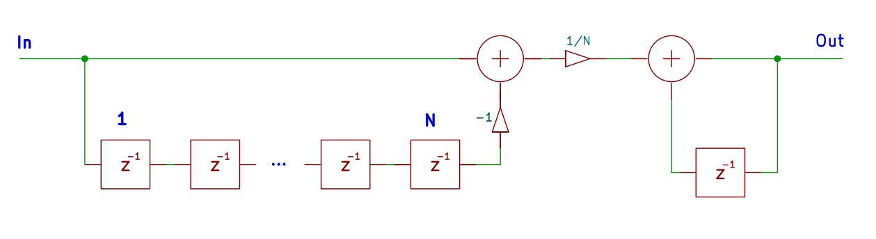
This filter structure is known as cascaded-integrator comb or CIC filter (a fancy name for the recursive implementation of a running average filter). If you want to learn more, you may have a look at
A Beginner’s Guide To Cascaded Integrator-Comb (CIC) Filters
In the diagram above the blocks labelled z-1 are delay elements and the small triangles represent multiplications.
The filter keeps a list of the N most recent input values. It adds the current value to a sum and subtracts the oldest sample from it.
Here are code snippets of a slightly different implementation which includes downsampling. T is a C++ template type. In our implementation it is std::complex<int32_t>. It should be noted, that this kind of filter only works for integer typed values. For float types rounding errors will lead to instabilities and saturation effects.
bool filterSample(const T& x, T& y)
{
m_sum = m_sum – m_history[m_hidx] + x;
m_history[m_hidx] = x;
m_hidx++;
if (m_hidx >= m_filterlength)
m_hidx = 0;
if ((m_hidx & 1) == 0)
{
y = T(m_sum.real() * m_fac, m_sum.imag() * m_fac);
return true;
}
return false;
}
The filter operation is performed in the first line of the function. The input value x is then pushed into the ringbuffer m_history. The following three lines are housekeeping for the index m_hidx. The if-statement at the end tests if the index is even and only if it is, computes the output value y and signals its validity to the caller by returning true as the function’s result. This results in a downsampling of the filtered sequence by a factor of 2.
A Cascaded CIC Filter
bool filter(T x, T& y)
{
bool rc = true;
for (DownSamplingFilter<T>* f : m_filters)
{
rc = f->filterSample(x, y);
if (!rc)
break;
x = y;
}
return rc;
}
Again, return value rc signals the validity of filter output variable y to the caller.
As every subsequent filter stage runs at ½ of the rate of the previous one, the computation load declines exponentially with each added stage. Increasing the number of stages therefore does not add significantly to the number of computations the MCU has to perform when a new sample comes in. Also, the length of the filter is irrelevant in this respect.
What we have to keep in mind, however, is the word length of the data type we use. If, as a worst case, the sequence of input values is a stream of 1s, the sum will be N and therefore requires ld(N) additional bits. This is one of the reasons why we left some headroom when computing the sine table as described in the previous chapter. The other reason is that the input values are the product of the ADC output samples and the table values. If we call the bit length of the table values T, the ADC bit length D, the filter length N then, to prevent overflows in the filter, the word length of our data type W must be larger than the sum of these three values
W > T + D + N.
Both the filter length N and the number of filters M in the cascade contribute to the settling time of the overall filter.
The settling time Tsettling can be computed as
Tsettling = N * 2M / Fsample
where Fsample is the sampling frequency of the ADC.
Obviously, the effect of the number of stages significantly outweighs that of the filter length.