In this part we are going to have a look at calibration and also see some test results.
Calibration
For the switching strategy described in the previous post only three parameters need to be known:
Rll the resistance of the „long loop“. This can be measured if all decades are set to zero and the bypass relay is not closed. The RDEC7 firmware provides SCPI command ADJustment:LLOop:CLOSe for this purpose. To update the parameter with a new measured value use command ADJustment:LLOop:RESistance <value>.
Rsl the resistance of the „short loop“. This can be measured if the resistance is set to zero. To update the parameter with a new measured value use command ADJustment:SLOop:RESistance <value>.
The relay contact resistance (effective resistance of two contacts in parallel). The value of the relay contact resistance is not very critical. I found that taking the value from the data sheet and dividing it by two is a good start. An optimum value can be found by finding the smallest maximum deviation for resistance values around 1 Ohm. This is where the effect of the relay resistance is most prominent.
To update the parameter with a new value use command ADJustment:RELay:RESistance <value>.
The calibration values can be set via remote control, as described here, or you can enter them manually on the calibration screens.
Test Results
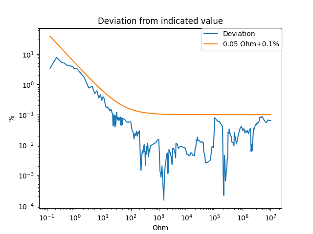
The above diagram shows the results of a test run over the complete range using the RDEC7 firmware. The blue curve represents the deviation of the measured resistance from the value displayed by the device. To the user the device presents itself like a calibrator. When setting a new resistance the firmware computes the actual resistance Ract including the remaining parasitics which could not be compensated and displays this value to the user.
The deviation stays below the orange limit line given by 0.05 Ohm + 0.1%. No other calibration other than the ones outlined above were necessary.
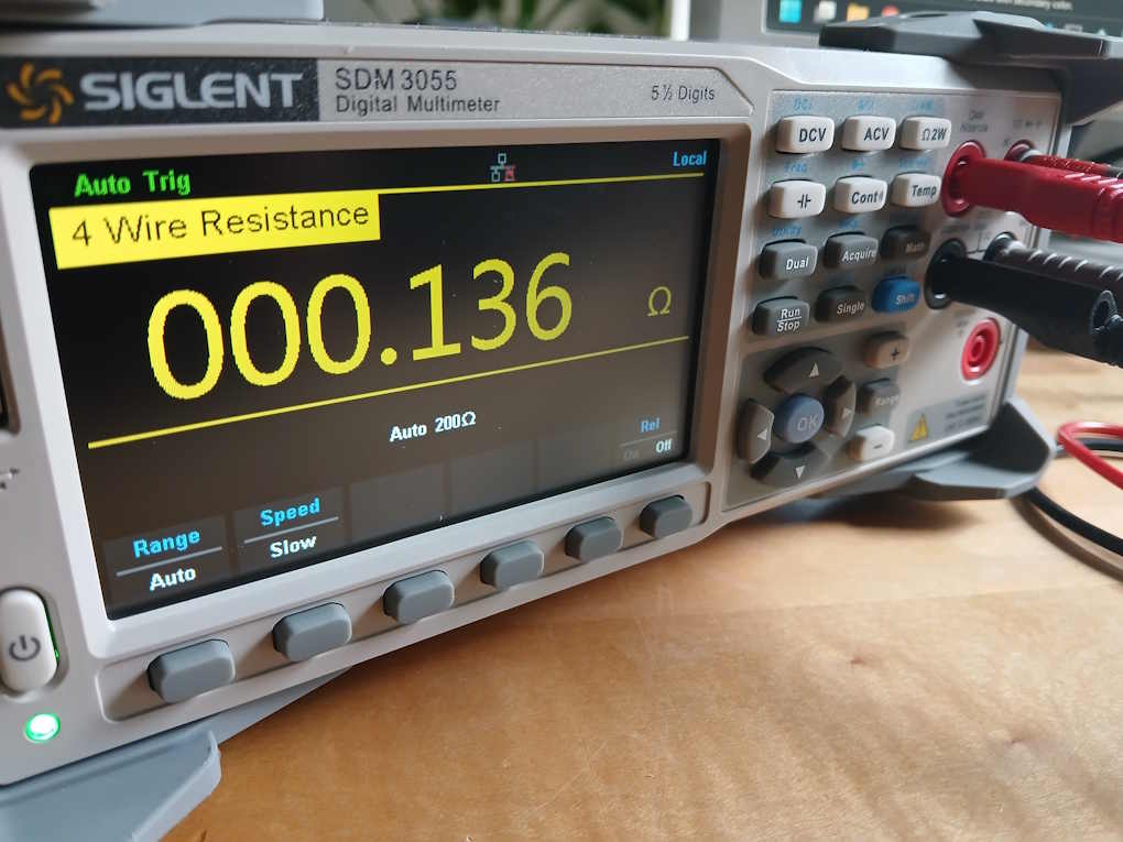
The measurements were taken with a Siglent SDM3055 5 ½ digit multimeter and a 4-wire test setup.
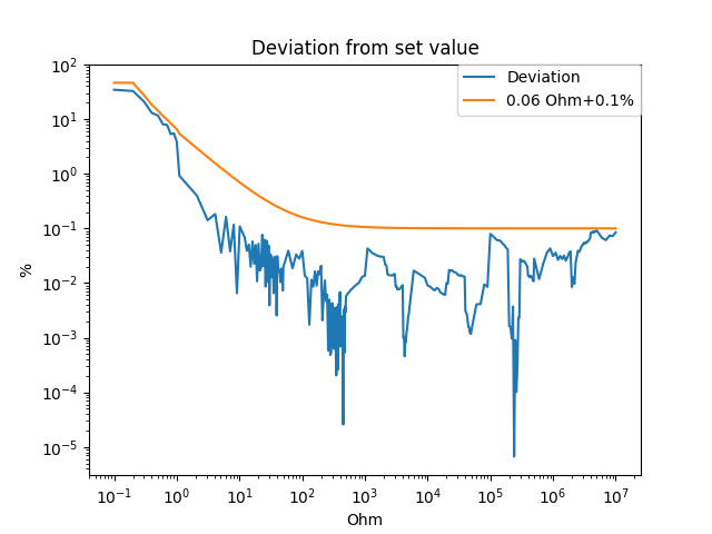
For small resistance values the deviation from the set value is slightly bigger than the deviation from the indicated value, which was to be expected. For resistances from around 50-100 Ohm onwards parasitic trace and relay contact resistances no longer contribute significantly to the measured values and both curves follow the 0.1% tolerance given by the quality of the built in precision resistors.
With more elaborate calibration and switching algorithms these values can certainly be improved upon. I’ll keep this as a topic for a future post (see Part 7).