In this part I am are going to take a dive into LCR measurement theory and finally derive formulas for computing measurement results and we will find a way to calibrate the device.
Measuring L, C and R
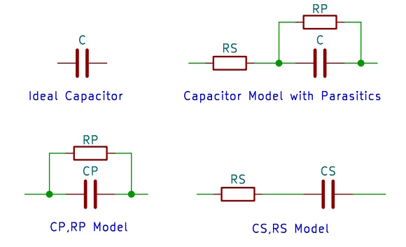
Every real resistor, capacitor or inductor comes with some kind of parasitic components. For example: its leads cause a capacitor to have some series resistance and the less than ideal insulation of its dielectric will act as a parallel resistance.
A realistic model of a capacitor will take both of these effects into account. (Even more precise models include the inductance of the leads and other effects.)
In practice, depending on which parasitic is more dominant, one of the two models, the serial model CS,RS or the parallel model CP,RP is used
Likewise, for inductors we have the LS,RS and the LP,RP models. RS in the serial models is also known as equivalent series resistance ESR, and can be found in many data sheets.
Interestingly, for a given measured impedance Z, if one solves for C, the two models return different values. So which model to pick, when measuring a component? Commercially available LCR meters chose the model for us automatically. From the manual of a Rohde&Schwarz LCR meter I derived this diagram, which gives a hint on how the selection is made in their instrument.
.
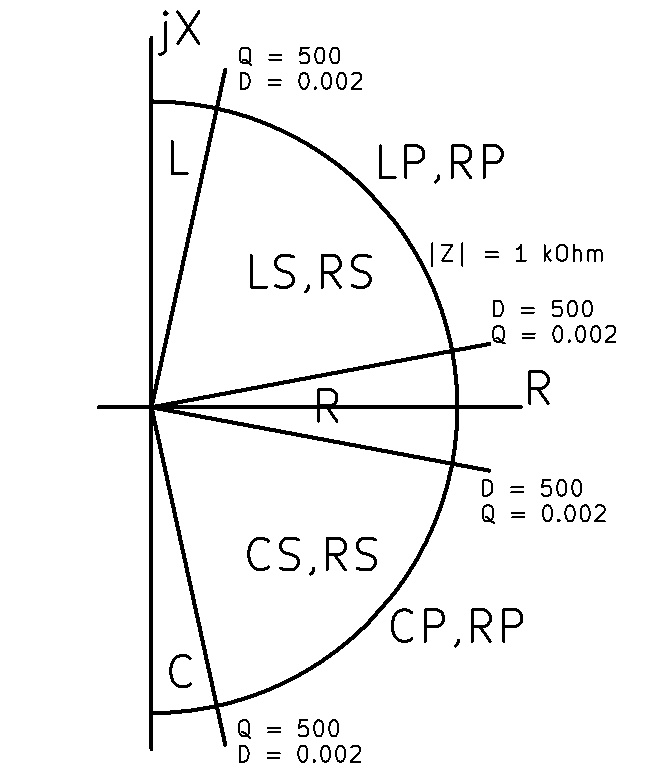
Given the real and imaginary parts R and X of Z, the dissipation factor D=R/|X| and the quality factor Q=1/D we can make these choices:
If D > 500 then this is a near ideal resistor with negligible parasitics
if Q > 500 then for X>0 this is a near ideal inductor with a negligible resistive part
if Q > 500 then for X<0 this is a near ideal capacitor with a negligible resistive part
if |Z|<1 kOhm then use a serial model, else use a parallel model
Measurement Types
LCR meters typically return measurements results as pairs of values. Many combinations/measurement modes are possible. For example:
| 1st \ 2nd | D | Q | RP | RS | X | θ | – |
|---|---|---|---|---|---|---|---|
| CP | x | x | x | ||||
| CS | x | x | x | ||||
| C | x | ||||||
| LP | x | x | x | ||||
| LS | x | x | x | ||||
| L | x | ||||||
| R | x | x | |||||
| |Z| | x |
Formulas
Given the measured values of R and X and the frequency f, we can now compute the measurement results we are interested in:
|Z| = sqrt(R*R + X*X)
ω = 2 * π* f
CP = -X / (|Z|2 * ω)
CS = -1 / (X * ω)
LP = |Z|2 / (X * ω)
LS = X / ω
D = R / |X|
Q = 1 / D
θ = atan(X / R)
For the computation of the “ideal” capacitance C and “ideal” inductance L the respective formula for the serial or the parallel model can be used as their results converge for a small enough R.
Open-Short Calibration
To compensate the effects of the test fixture we can perform calibration measurements. One with the leads open and another with the leads shorted yielding the impedances Zo and Zs respectively.
We can use these values to perform corrections on the measurements. If we are using a serial model we simply subtract Zs from the measured impedance to get the result Zr.
Zr = Zm – Zs
In a parallel model the open impedance Zo is in parallel to the DUT so we have to compute
Zr = (Zm – Zo) / (Zm * Zo)
to get the result Zr. If both Zo and Zs are available we can use
Zr = (Zm – Zs) / (1 – (Zm * Zs) / Zo)
Calibration
The set can be calibrated in a two stage process:
Calibrate gain and phase for all stages of the voltage amplifier
Calibrate gain and phase for all stages of the transimpedance amplifier. Compare measured resistance with a set of resistors whose values are known.
For the first step we need a set of resistors, one for every stage of the voltage amplifier. Their values are not critical, as their only purpose is to set the amplitude of the voltage ADC. For each of the measurement frequencies 100Hz, 120Hz, 1kHz and 10kHz, record the amplitude and phase of the voltage channel. (The measurement bridge must be balanced for the voltages to be valid, of course.) To make sure the gain stages are consistent we measure the voltage for the selected stage and also for the previous one and make corrections to ensure a smooth transition between stages.
As the absolute value of the voltage does not matter when we compute the impedance, one one the frequency/gain stage combinations (e.g. 1kHz/stage 1) can be defined as the reference and all other calibration values can be stored as values relative to it.
For the second step we again need a set of resistors, one for every stage of the transimpedance amplifier. The values of these resistors need to be known. They will serve as the reference to calibrate the absolute values of our measurements.
For each step measure level and phase of the current channel. Compute the resistance value by dividing the (now corrected) voltage by the measured current. Compare this value with the known resistance for this stage and record the deviation.
As we attached a pure resistor to the device, we expect to see a phase angle of 0 degrees. Therefore subtract the measured phases of voltage and current and store this value as the phase deviation. Repeat this procedure for every frequency.