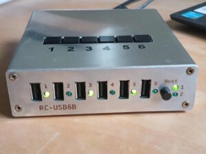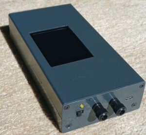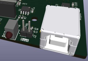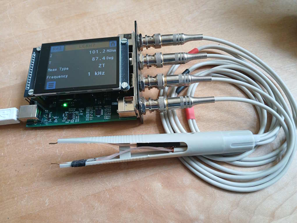
Based on the ideas developed so far I built a prototype.
A Prototype
These were the design decisions I made for the prototype:
Measurement frequencies: 100 Hz, 120 Hz, 1 kHz, 10 kHz
Sampling frequency 200 kHz or higher
STM32H7 MCU for enough computing power for the planned sampling frequency. Also, this MCU has a 16-bit ADC as opposed to e.g. the 14-bit ADC the F4 series has.
BNC connectors for connecting a Kelvin probe
OPA3S328 for the transimpedance amplifier
TMUX1108 multiplexers for switching the gain
USB-B connector for power and remote control
2.8” capacitive touch screen for the GUI
The prototype was useful to get an idea of the issues involved with measuring impedances. Also, I was able to verify the concepts of the lock-in amplifier and the CDC filter. Both performed as expected.
To calibrate the device I tried to use the decade resistor box I made earlier. This worked well up to around 1 MOhm when the effects of parasitic capacitances kicked in and the results were no longer reliable. (As a reference I used my DER EE DE-5000 LCR meter.)
I therefore resorted to sets of discrete SMD resistors which I assembled on a small PCB and connected to the device during calibration.
This worked quite well. I ran into several issues, however, for some of which I at first had no explanation at all.
The capacitance error
When measuring capacitors in the high nF region I observed significant differences between the results delivered by the device and that of the DE-5000. After hours of experimenting I found out that the DC bias voltage which the device puts on its leads (intended for polarized capacitors) was the cause of this effect. The effect which is especially pronounced in X7R MLCC capacitors is well known but here I was experiencing it first hand. This white paper by Kyocera explains it quite well.
DC Bias Characteristics of Ceramic Capacitors
To test, if I could provoke the same reading on he DE-5000, I put a battery in series to the capacitor and, lo and behold, the DE-5000 showed similar results.
With the next revision of the device it will therefore be possible to switch the DC bias on or off.
The transformer issue
The inductance measured on a mains transformer deviated significantly from what the DE-5000 said. Again, I was trying to find out what the differences in the measurement setup could be. What immediately comes to mind is the internal resistance of the device which I set to be 270 Ohm. The internal resistance of the DE-5000 on the other hand seems to be around 110 Ohm.
Changing the internal resistance of the device to 100 Ohm brought the readings much closer. Obviously, due to the properties of the iron core the inductance is highly dependent on the current used by the instrument. My takeaway from this experience is that measurements on inductors with iron cores are not comparable across instruments. You may also read
Inductance measurements can be confusing – a deeper dive
which highlights this with this parable:
An apprentice asked: “Master, I measured the value of an inductance and it was X. Is this correct?” The master replied: “It is correct.” Then the second apprentice said: “But I measured the same inductance and the value was Y, am I wrong?” And the master answered: “You are also correct. Indeed, you are both correct.” The third student objected: “They cannot be both right if the two results differ!” And the master agreed: “You are also correct.” All three students were perplexed…
GBW
The gain-bandwidth product of the OPA3S328 is 40 MHz, which limits the available gain for the 10 kHz measurement frequency. In the next revision of the board I therefore intend to use a 2-stage amplifier design.