I continue with the design of the LCR meter, draw a simplified schematic of the box and design the C-code for a DDS generator we can use for hardware and software.
The 4-Wire Connection
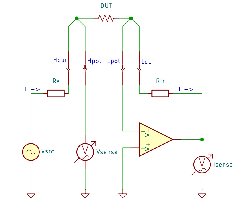
The auto-balancing bridge we started out with can be improved. For better accuracy, when measuring small resistance values, ohmmeters make use of the four-wire technique using a Kelvin connection. This minimizes errors due to the lead resistances.
Here, the DUT is connected with one pair of wires, labelled Hcur and Lcur, which carry the current and a second pair of wires, labelled Hpot and Lpot, which sense the voltage at the DUT. We are going to use this method too.
The overall signal flow will now look like this.
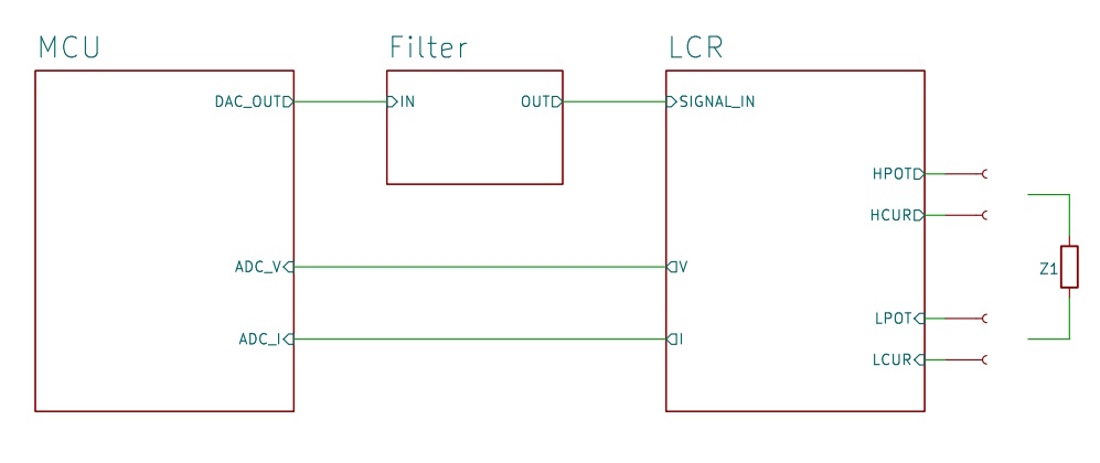
The MCU generates a sine signal which is converted to the analog domain using its DAC. To remove high frequency components we pass it through a low pass filter before it gets to the measurement bridge. The bridge outputs the two signals V and I which are fed back to the MCU which converts them to the digital domain for further processing. The DUT is connected to the bridge using a four-wire connection.
The filter is a simple two-stage active filter which I designed with the help of Analog Devices’ Analog Filter Wizard
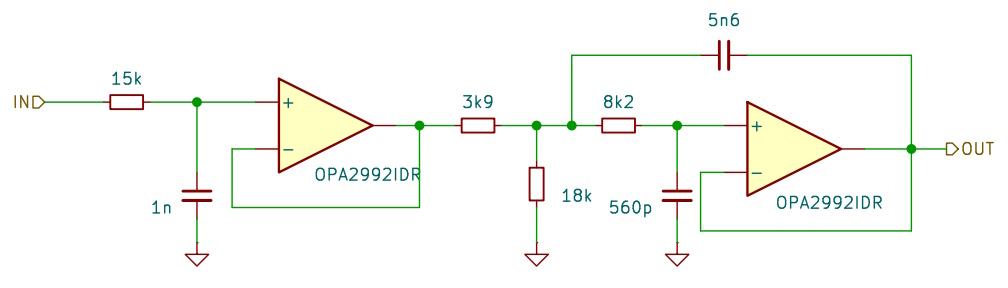
The requirements for this filter were: passband up to 10kHz and 40 dB attenuation at 100kHz which is half of the sampling frequency of 200kHz which I had in mind as the minimum.
Amplifiers and Multiplexers
The opamp in our bridge converts current I into voltage Isense. This kind of function is the domain of transimpedance amplifiers. There are special chips on the market which especially target this application and we are going to use one of them in our project. I picked type OPA3S328 from Texas Instruments. This component includes two amplifiers and two sets of switches which can be used to select amplifier gains. It is a rail-to-rail chip with a maximum supply voltage of 5.5V.
We are going to use one of the amplifiers as the transimpedance amplifier in the bridge. The other one will be used as an amplifier for voltage Vsense across the DUT.
We need to be able to set the gain of both amplifiers in a wide range. To accomplish this we need to change the value of the feedback resistors using multiplexers. (The switches in the OPAS328 cannot be used for small resistors as their on-resistance is on the order of 100 Ohm.) The multiplexer I chose is type TMUX1108, a 8:1 multiplexer with an on-resistance of only 2.5 Ohm. It also supports rail-to-rail operation and can work on low supply voltages.
Bringing all this together we can now draw a simplified schematic of the bridge with amplifiers and multiplexers.
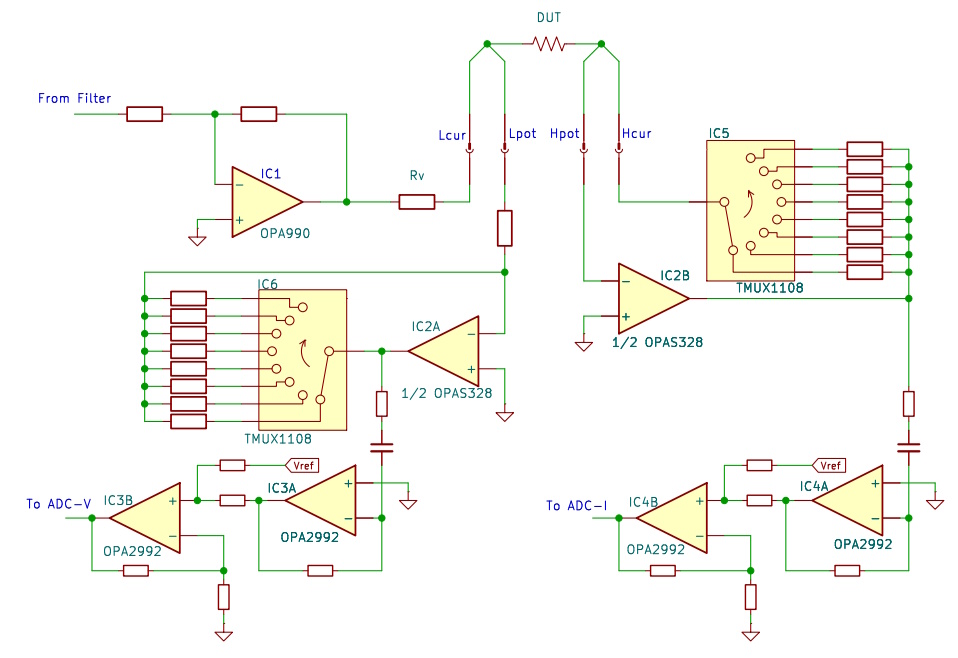
IC1 buffers the signal coming from the filter and allows for amplitude corrections if required. IC2B together with multiplexer IC5 is the variable gain transimpedance amplifier. IC4 strips away the DC content of the signal and adds Vref/2 to it. Thus the resulting signal sits in the center of input voltage range of the ADC. IC2A together with multiplexer IC6 is a variable gain amplifier which amplifies the voltage across the DUT. An identical circuit as the one built with IC4 prepares the output signal for the voltage channel ADC.
A DDS Signal Generator
We use a Direct Digital Synthesis algorithm to create the sin and cos components of the signal we need to stimulate the DUT and for the computations in the LIA algorithm.
An excellent paper on DDS can be found at https://www.analog.com/media/en/training-seminars/tutorials/450968421DDS_Tutorial_rev12-2-99.pdf
In a nutshell, this is what we do.
Create a table with the sin-function values for 1 ¼ periods. (This is because we want to get sin and cos in one lookup and we use a fixed index offset of ¼ period to retrieve the cos-component.)
Set up a phase accumulator. This is a fixed point value with a fractional and an integer part. The integer part is used as the index in the table. The fractional part improves the frequency resolution of the algorithm.
Set up a phase increment register. This register has the same format as the accumulator. Its content is added to the accumulator after each table lookup.
Here is a piece of code:
enum{TABLEPERIODBITS = 9}; // period = 512
static constexpr size_t TABLEPERIOD = (1<<TABLEPERIODBITS);
static constexpr size_t TABLESIZE = TABLEPERIOD*5/4; // 1+1/4 period for easier
sin+cos lookup
static constexpr size_t FRACBITS = 32 – TABLEPERIODBITS;
static constexpr int32_t SINCOSFAC = 2048;
uint32_t m_phaseAccumulator;
uint32_t m_phaseIncrement;
int32_t m_sincostab[TABLESIZE];
void createTable()
{
double deltaphase = M_PI * 2 / TABLEPERIOD;
for (size_t i = 0; i < TABLESIZE; i++)
m_sincostab[i] = (SINCOSFAC-1) * sin(i * deltaphase);
}
void setFrequency(double frequency)
{
double f0 = m_fsample / TABLEPERIOD;
m_phaseIncrement = ((frequency *(1<<FRACBITS)) / f0) ;
}
std::complex<int32_t> getSinCos(int32_t idx)
{
int32_t s = m_sincostab[idx];
int32_t c = m_sincostab[idx + TABLEPERIOD/4];
return std::complex<int32_t>(c, s);
}
// lookup and incrementing the phase
std::complex<int32_t> sc = getSinCos(m_phaseAccumulator >> FRACBITS);
m_phaseAccumulator += m_phaseIncrement;
We do not use all bits of the table but restrict the amplitude to SINCOSFAC to leave some headroom for the bits added by the processing further down the processing chain.