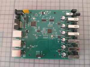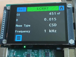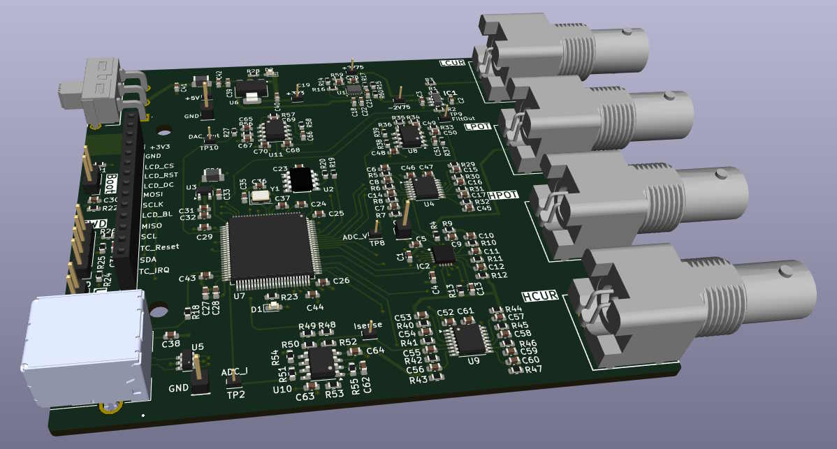
Is it possible to build an LCR meter without an FPGA or any fancy DACs, ADCs and DDS chips for signal generation, just using the analog capabilities of the MCU, a handful of opamps and a few multiplexers? This project is trying to find out if we can build an LCR meter with a STM32 microcontroller based on the principles of a lock-in amplifier. So let’s see, how far we can get using this approach and what we can learn in the process.
Impedance Measurement Basics
There are a great many introductions to LCR measurements out there in the Internet. If you are not familiar with the concepts or need a refresher you may, for example, have a look at
An LCR meter measures the complex impedance Z of a resistor, capacitor or inductor connected to its terminals. One way of doing this is to apply a sinusoidal signal to the component and measure the complex voltage V across it and the complex current I which passes through the component.
The impedance Z can then be computed as Z = U/I.
From Z and the frequency of the applied signal we can then compute the component’s resistance, capacitance or inductance as well as other quantities like phase angle, dissipation factor asf.
I will get back to the computation of these quantities later.
The Auto-Balancing Bridge
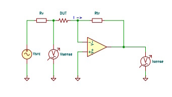
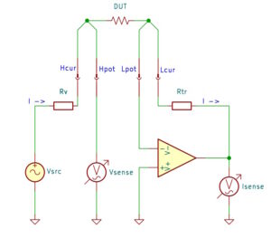
To measure the impedance of our DUT we use an auto-balancing bridge. Sinusoidal voltage Vsrc is applied to the DUT via series resistor Rv. Because the opamp operates in its linear region, the other side of the DUT sees a virtual ground and Vsense therefore is the voltage across the DUT. The complete current through the DUT passes through the opamp’s feedback resistor Rtr creating voltage Isense at the output of the opamp. Isense can be computed as
Isense = -I * Rtr and therefore I = -Isense/Rtr
and the impedance Z of our DUT becomes Z = -Vsense / I = -Rtr * Vsense/Isense .
Note that neither the source voltage Vsrc nor the series resistance Rv shows up in this equation. This lets us hope that we can achieve our goals without the need for a very sophisticated signal generator.
Measuring Complex Quantities – The Lock-In Amplifier
Now that we have a hardware setup that allows us to measure voltage and current, we need to think about how we can measure these as complex quantities.
One way to measure the complex output of a system at a given reference frequency is the Lock-In Amplifier
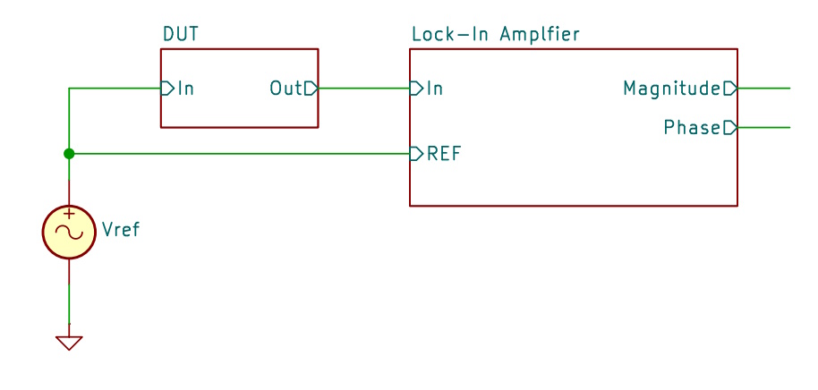
A Lock-In Amplifier LIA is a system which takes the output of the DUT and, together with the reference signal which was used to stimulate the DUT, computes magnitude and phase of the input signal. An additional benefit of the LIA, and in many applications its main use, is its ability to suppress all signal components which are not synchronous to the reference frequency. This comes in handy here too as we will have to measure very small voltages and currents.
If we compare this setup with the auto-balancing bridge diagram above we see that we very well can use LIAs here. To measure voltage and current we need two LIAs, one for each of these quantities, with Vsrc serving as the reference signal.
Using two LIAs we measure |V|, Φv and |I| and Φi, the respective magnitudes and phases of V and I. The magnitude of impedance Z can then be found by dividing the magnitudes of V and I and its phase by subtracting their phase values.
|Z| = |V| / |I|
Φz = Φv – Φi
Lock-In Amplifiers Internals
So how does a Lock-In Amplifier work? Again, there are lots of resources on the Internet which explain LIAs in detail. For example, you may go to
Zurich Instruments: Principles of lock-in detection
to learn more about LIAs.
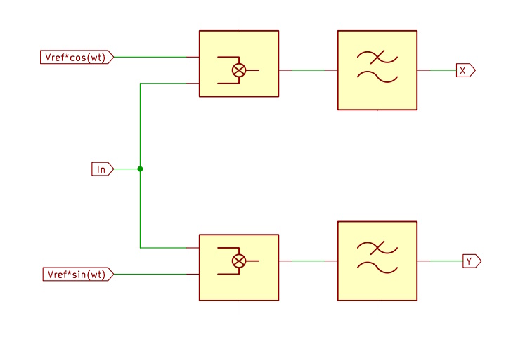
Internally a LIA uses two multipliers and two low pass filters to compute the average of the real and imaginary parts, X and Y, of the products of the input signal and the two orthogonal reference signal components Vref*cos(ωt) and Vref*sin(ωt). From the real and imaginary parts X and Y we can easily compute magnitude |V| and phase Φ by
|V| = sqrt(X*X + Y*Y)
Φ = atan(Y/X)
For our purposes this means:
- We need a signal generator which outputs both sin and cos components. The MCU can create the signals using a sine table and a DDS algorithm. One of the components will be converted to an analog signal and will stimulate our DUT. Both components are used in the digital signal processing of the LIA algorithm
- As the signal processing is going to be in the MCU, the multiplications are performed in software. This requires that the input signal has been converted to the digital domain by an ADC. We are going to be using the ADC of the MCU for this task.
- Four low pass filters (real and imaginary parts for both voltage and current) are required. These filters very much determine the performance of the LIA. A low order filter offers short response times when measuring time-varying signals while a high order filter is slower but has better noise suppression. As our measurement signals are nearly static in nature we will go for filters with long impulse responses. We will see later, how such digital filters can be built using the modest resources of a microcontroller.