Building the device.
Building the Device
To build the device proceed as follows:
Download Fabrication Documents
The fabrication documents are available for download here. The archive includes:
- Schematics as PDF and KiCad files
- BOMs as CSV files
- Gerber files ready for upload to a manufacturer
- 3D-views of front and backside of PCBs
- Fab-layers in the Gerber file set for easier parts placement
- Firmware binary with download instructions
- Python skript for adjustment and test
- Documentation
Order Parts and Have PCBs Manufactured
To build the device order the parts from your favourite supplier (LCSC, Mouser, DigiKey etc.). Make sure to get a Li-Po battery with a built-in protection circuit. Also, make sure the TFT display is one with the capacitive touch driver chip FT6336, not one of the abundantly available resistive touch displays, as these won’t work here.
Have the PCBs manufactured by a PCB manufacturer. My PCBs were made by JLCPCB and they turned out perfectly.
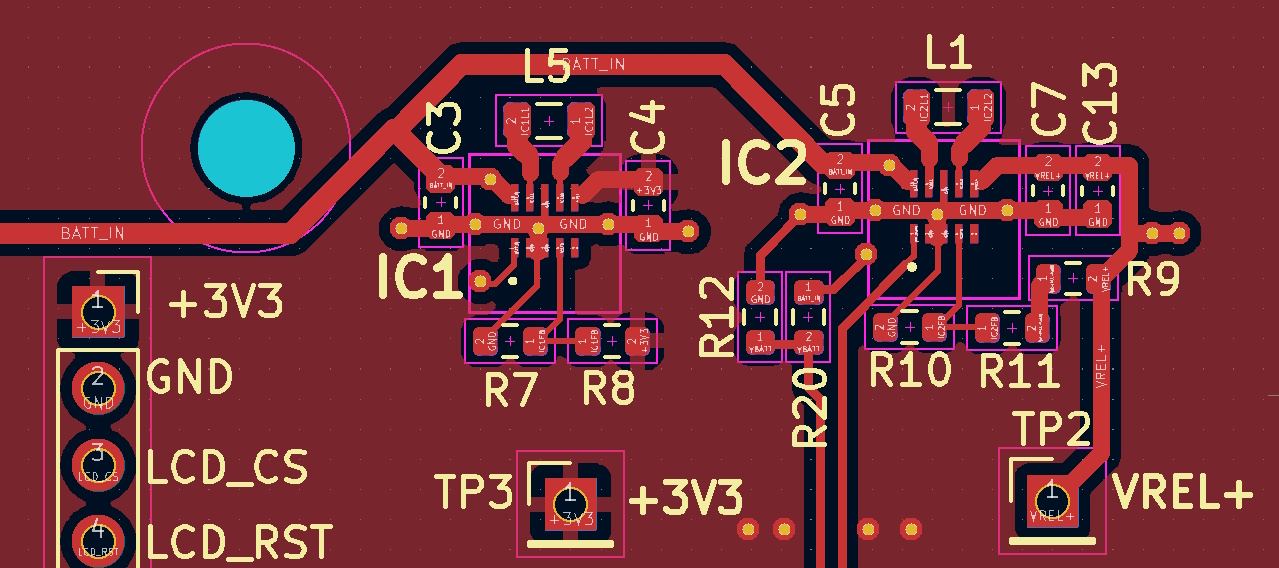
Solder PCBs
Soldering the boards should not be too difficult unless this is your first project. The standard component size is 0603 which should be easy to solder.
The only parts which need some attention are the voltage regulator chips TPSD63802 which come in tiny 3×2 mm packages. Reduce the air flow on your heat gun when soldering these parts to avoid them getting blown away.
Also, it is advisable to start with the power supply section on the controller board before placing the MCU and the other parts to avoid that these are getting fried if the converter chips are not working properly.
Program Firmware into the MCU
If you are familiar with programming ST’s MCUs you can write your own firmware. The board has a debug interface and the documentation includes all the informations required. For everybody else it will be easier to install the binary which comes with the download package.
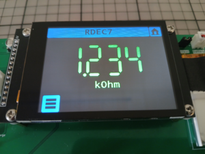
Download STM32CubeProgrammer from ST’s website and follow the instructions in the HowTo document to program the firmware into the MCU. The green LED on the board should start pulsating if the firmware is up and running. The firmware is time limited and stops after 30 minutes. To continue you have to restart the firmware. This limitation can be removed by entering a registration key which you can get for free if you send me an email with the device’s serial number. The serial number is displayed on the About screen or returned as part of the SCPI IDN-string.
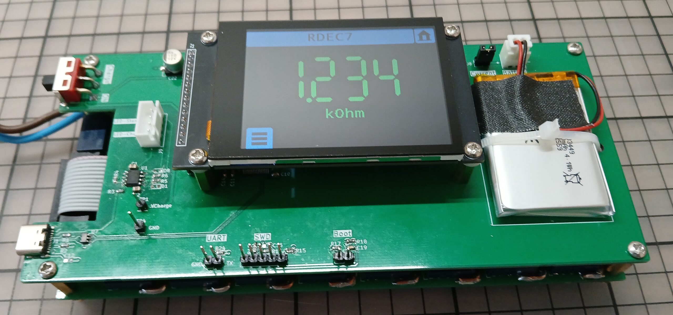
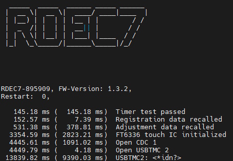
Using the UART interface
The UART interface can help when bringing up the device. It outputs status information which can be useful for troubleshooting. Connect a serial interface with settings 115200/8/N/1 to the TX pin.
Calibration and Test
The device should work with decent accuracy with the default adjustment parameters in the firmware. For improved results use the simple calibration method described in Part 2 of this blog or use function AdjustStageResistances in the Python skipt RDEC7-Test.py in the download package. To use this function you need a DMM which can be remote controlled via USBTMC or LAN. If you have not done so already, install a Visa library from Rohde&Schwarz or NI and install PyVisa in Python before running the skipt.
To test the deviation use function TestDeviation in the same module.
Enclosure
I tried in vain to find an enclosure which would fit snugly around the device so I decided to build my own. For the top and bottom I bent two pieces of 1.5 mm aluminum sheet metal into U-shapes. The front and back plates are made of thinner 1 mm aluminum. They are held in place with M3 screws. The top screws sit in threaded pieces of PVC which I glued into the corners . The bottom screws go into L-shaped pieces of aluminum sheet metal which are attached to the standoffs.