Working as a software developer for the Test&Measurement industry I often needed to connect and disconnect various USB devices to and from a host system. There are USB-hubs on the market which can do this but I was not really satisfied with what we had. As I had only recently reactivated my hobby of building electronics I wanted to see if I could not do a better job and create a hub which would be more versatile than the ones we had.
Overview
This is what I wanted from such a hub:
- 6 downstream ports
- 2 upstream ports
- separate control port
- remote controllable from any OS via USB without any specific driver
- being able to switch data and power lines separately
- optional control using buttons
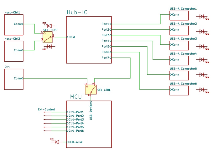
This is the block diagram of the hub. The two main components of the device are the hub-IC and the MCU. The hub-IC, a USB2517 from Microchip supports 7 downstream ports, 6 of which are routed to the 6 USB-A connectors on the front panel. The upstream port of the chip can be connected to one of the two USB-B connectors labelled “Host/Ctrl 1” and “Host/Ctrl 2”. The host port can be selected by a push button on the front panel or by software.
The on-state of a port is signalled by its LED. The MCU controls the states of the ports through several solid state switches which are not drawn here. It receives commands from its USB port which is either connected to a dedicated USB-B connector, labelled “Ctrl” or to port 7 of the USB-Chip. In the latter case the host has two roles: it controls the hub and at the same time is the host to devices on the downstream ports.
The scenario where the MCU is connected to USB-B port “Ctrl” is for setups where the devices need to be connected to host-DUTs on ports “Host/Ctrl”and the hub is controlled by a PC on host-port “Ctrl”.
The state of the ports can also be controlled by external pins. This allows for hardware control of the hub and by connecting pushbuttons to the control lines, it is possible to switch the ports on or off manually.
Port Switching
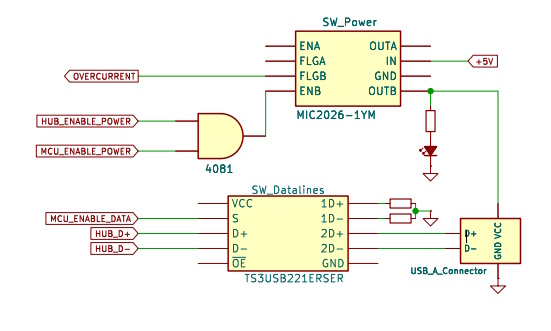
The design allows to switch port power and data lines independently for each port using MIC2026 chips for the power and TS3USB221 chips for the USB data lines.
The MIC2026 switches on power to the connector if the hub chip USB2517 pulls HUB_ENABLE_POWER high and the MCU enables MCU_ENABLE_POWER. The MIC2026 monitors the current and asserts OVERCURRENT in case of an overcurrent or thermal shutdown conditiona to signal it to the hub chip and the MCU.
The differential data lines HUB_D+ and HUB_D- are passed through a DPDT USB switch TS3USB221 before going to the USB connector. The switch is controlled by the MCU by signal MCU_ENABLE_DATA. In the off state the data lines are routed to two terminating resistors to avoid reflections on the bus.
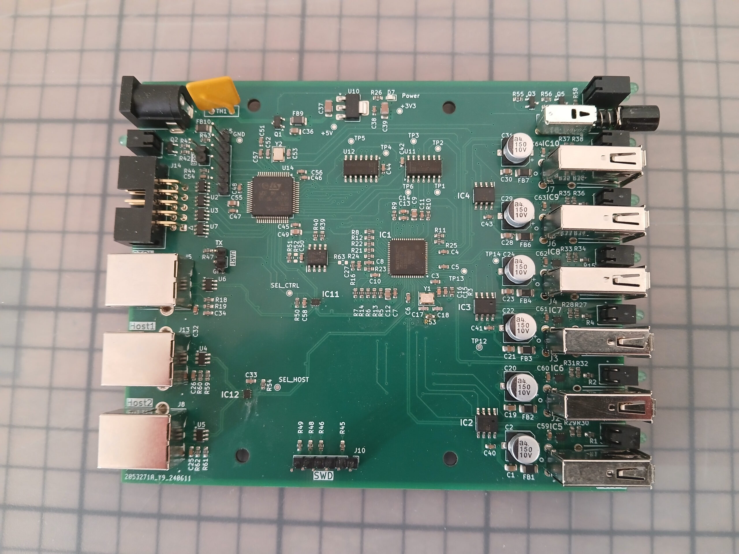
The Board
The PCB is a four-layer board of 120x100mm with single sided assembly. With these dimensions it just fits into a Hammond extruded aluminum enclosure. All connectors and controls are on the front and back side.
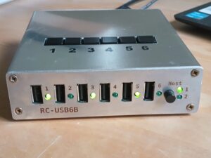
Front
- Six USB-A device connectors, each with its 3mm LED to signal the port’s state.
- A non-latching pushbutton to toggle the host.
- A pair of LEDs to indicate the selected host.
Back
- A barrel jack connector for the 5V power supply.
- A LED indicating the “alive” state of the device.
- A 2×5 pin IDC header for the external control signals.
- 3 USB-B connectors “Host/Ctrl1”, “Host/Ctrl2”, and “Ctrl”
All external connections are protected by ESD diodes. The power supply is reverse polarity protected.
On The Board
There are 3 sets of pin headers to be used for debugging and device bringup:
- A SWD debugging interface to be used with ST-Link.
- A 2-pin UART interface which outputs debugging messages.
- A 2-pin boot connector which, if bridged on power up, starts the MCU’s bootloader.
The microcontroller is a 64-pin STM32F446RE with an attached CAT24C256 Eeprom for permanent data storage.