This post is about the Relay Board.
Relay Board
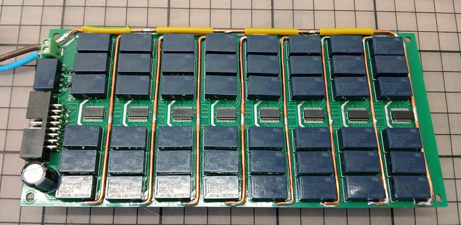
The relay board is an inexpensive double-layered PCB with standard copper weight. To keep the board size small assembly is from both sides. Thick copper wires have been added to half of the traces connecting the decades to reduce parasitic resistances. (Putting a thick glob of solder on a trace is not enough as the conductivity of solder is substantially lower than that of copper.)
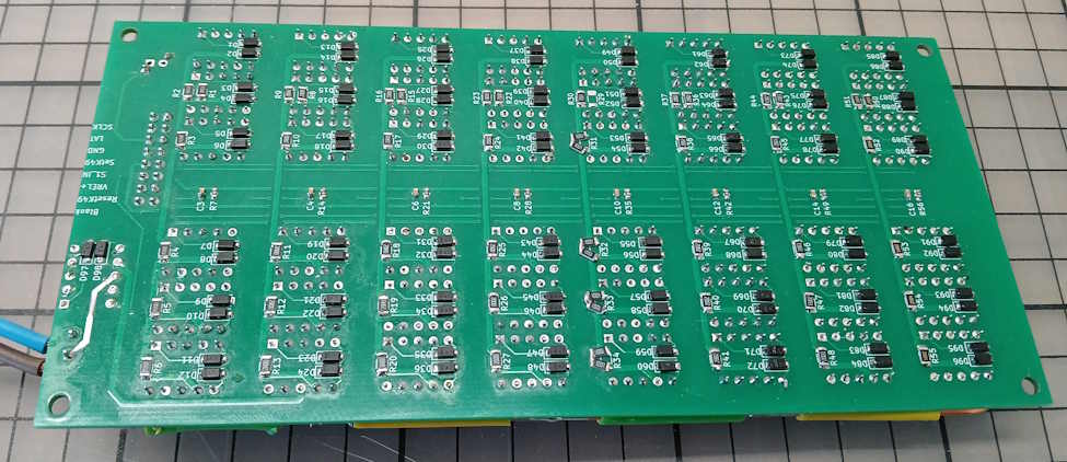
The relays are Panasonic TQ2-L2-5V latching relays with two coils driven by constant current LED driver chips TLC59284DBQ from Texas Instruments. Each of these chips can drive up to 16 channels of which we use 12 for the 6×2 coils of the relays of each decade. The driver current is set to ~30 mA.
Relay Power Considerations
If all 49 relays on the board are powered at the same time this adds up to 1.5 A which the power supply circuitry will have difficulties to provide even if this current is only required for the short time it takes to flip the state of a relay.
Taking a closer look at the schematic of a decade we can set up this table
n / SW 1 2 3 4 5 6
———————–
0: 1 1 X X X X
1: 0 1 X X X X
2: 1 0 1 X X X
3: 0 0 1 X X X
4: 1 0 0 1 X X
5: 0 0 0 1 X X
6: 1 0 0 0 1 X
7: 0 0 0 0 1 X
8: 1 0 0 0 0 1
9: 0 0 0 0 0 1
where 0 = off, 1 = on, X = don’t care
If, for example, a decade value of 2 is required the relays 1,2,3 must be set to 1,0,1 respectively. The states of relays 4,5,6 do not matter, so they need not be switched.
Further reductions on power consumption can be made if we keep track of the current state of each relay. A relay only needs to be energized if its state must be flipped.
In cases where the majority of relays needs to be set the decades are switched sequentially to avoid overloading the power supply.
Implementing Switching Modes
For some applications it is necessary that the transition from one resistance to the next takes place in a controlled manner. These modes are commonly known as “Break Before Make” or “Make Before Break” modes.
- Make Before Break: the loop never becomes open when switching from one resistance value to the next.
- Break Before Make: The loop is guaranteed to be opened when transitioning from one settings to the next.
Impelementing these modes is very straightforward. For Make Before Break we close the vertical relay switch which must be closed in the new configuration on top of the vertical relay switch which is already closed. In a second step we then apply the new configuration which will cause the old relay switch to be opened.
Implementing Break Before Make is even easier. In a first step we simply open all relay switches in the first decade and only then apply the new setting.