In this episode I am going to talk about building the box.
Building the Device
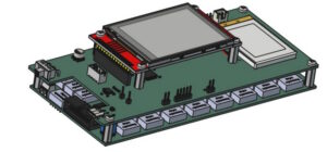
The relay board is a double sided PCB which I had manufactured by JLCPCB. I soldered all the parts myself. I also ordered a new revision of the control board which fixes some issues of the initial revision.
Schematics, Gerber files and firmware can be downloaded from the Download section.
Choosing the Capacitors
I wanted the relay board to be of the same size as the one of the resistor decade but for stability reasons I also did not want to use electrolytic or X5R or X7R capacitors although they come in smaller packages. This meant using the bulkier film capacitors for the larger values and a maximum value for the set capacitance of 100uF.
These are the capacitors I used:
20p: 1%, 100V, C0G, 0603 from Murata
200p: 1%, 100V, C0G, 0603 from Murata
2n: 1%, 100V, C0G, 0603 from Murata
20n: 1% 50V, C0G, 0805 from Murata
100n: 5%, 100V, Film, TH from Walson
200n: 5%, 100V, Film, TH from Kyet
1u: 5%, 100V, Film, TH from Knscha
2u: 5%, 100V, Film, TH from Kyet
10u: 5%, 100V, Film, TH from Xiamen Faratronic
When building and calibrating the device I realized that it would have been a good idea to order more than just the minimum required number of capacitors. The values of some of the batches, although within the 5% tolerance, were clustered not around the nominal value but to a value significantly above that. This made it difficult to select items with optimum values. Also, ordering batches from more than just one manufacturer might have helped.
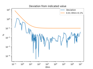
To test for any glitches I ran an automated test on a very dense grid. For this I used my SDM3055 multimeter which is less accurate than my LCR meter and can only be used for values greater than 1nF but can be controlled remotely.
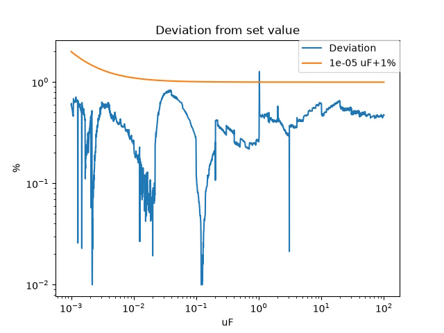
As can be seen, there is a single glitch at 1uF which is caused by the 1uF capacitor whose value is too high and needs to be replaced by one with a smaller capacitance. The firmware uses the capacitor values when computing an actual value so the deviations from the actual values are within limits. Still, this needs to be fixed when the next shipment of components arrives.
Building an Enclosure
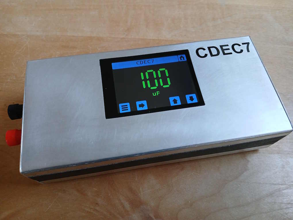
As with the resistor decade I built an enclosure by bending two pieces of 1.5mm aluminium sheet metal into U-shapes and screwing front and back plates onto small L-shaped pieces of aluminium which I glued / screwed to the bottom and top.
Download
Schematic, Gerber files and firmware are available in the Download section.