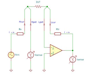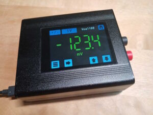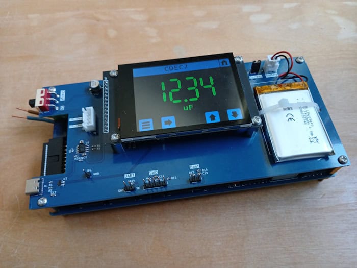
This is a follow up project to my Programmable Decade Resistor project. This capacitor box can set capacitances from 20pF to 100µF in steps of 10pF.
Overview
When building the programmable decade resistor I split the system into two PCBs: the controller board which is reused in this project and the relay board. For his project I designed a new relay board with capacitances instead of resistors. The relays and the driver chips are of the same type as before. However, varying capacitances means connecting components in parallel instead of in series as with the resistor box, so the topology had to change.
These are the features of the box:
- Capacitances from 20pF to 100µF in steps of 10pF
- Using latching relays, which will keep their settings without being powered
- Rechargeable, single cell Li-Po battery
- 2.8“ capacitive touch display (no buttons or rotary encoder)
- Remote control via USB
System Topology
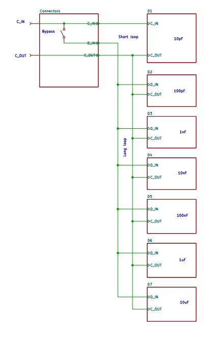
The overall system consists of 7 decades. The step sizes of the decades go from 10pF to 10uF. A bypass relay can decouple decades 2 through 7 from the output connectors which reduces the effects of parasitic capacitances of the “long loop” which would otherwise dominate the overall capacity in the pF range.
With the bypass relay active (i.e. open), only decade 1 is active forming the “short loop”. The parasitic capacitance of the short loop is around 20pF which determines the smallest capacitance value which can be set. The parasitic capacitance of the long loop, (i.e. when the bypass relay is closed) is around 87pF. This values is smaller than the maximum value which can be set by decade 1 so we can compensate the long loop parasitic capacitance with decade 1.
Decade Topology
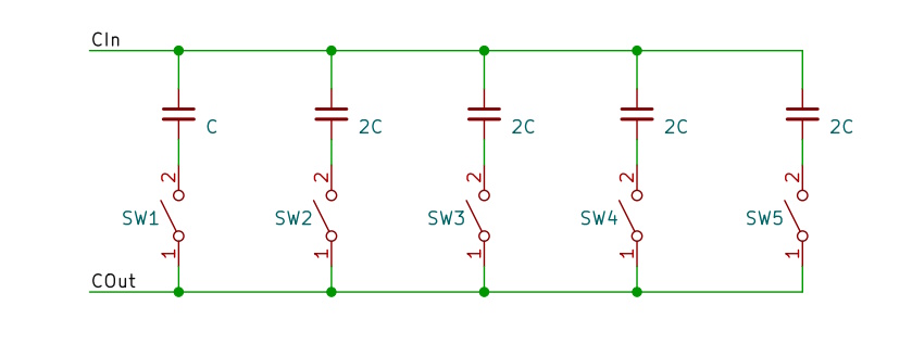
Each decade has 5 capacitors which can be switched in parallel by 5 relays. Unlike with the topology in the resistor box we here have more options in how to set a specific value.
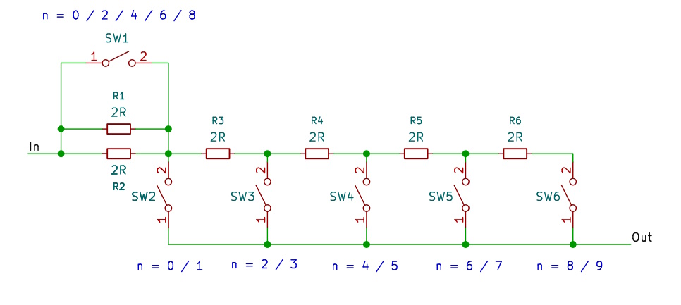
For example: to set a resistance value of 5, SW4 must be closed whereas for the capacitor decade we need to close SW1 and additionally (SW2+SW3 or SW2+SW4 or … ). This flexibility can be used to improve the accuracy of the setting.
Switching Strategy
Unlike with the 0.1% resistors in the resistor box the capacitors used here come with much larger tolerances of up to 5%. Also the capacitance values within one batch vary widely. Continuing the example above we therefore need to find the best alternative SW2+SW3 or SW2+SW4..
Perhaps the problem of approximating a set capacitance can be made clearer with the following analogous task:
“Given a set of sticks of varying lengths and an interval. Find a set of sticks which, put end to end, are the best approximation of the interval”.
Trying out every combination will yield the best result but depending on the number of sticks and the length of the interval this may take too long and may therefore not be feasible. In our case this is certainly not an option. Instead, the following algorithm may be used:
“Sort the sticks by length. Beginning with the longest stick, if the stick fits into the remaining interval, place it else continue with the next stick until no more sticks are left.”
To apply this algorithm to our problem we try the capacitances of decades 7-1 with decade 7 first. Next, in each decade we sort the decade capacitances at SW1-SW5 in decreasing order and test one after the other starting with the largest. If the current sum + the tested capacity is smaller than the set value we switch on the corresponding relay and increment the current sum by the value of the tested capacity.
Note: As the capacitor at SW 1 is smaller than the others in the decade it fits nicely into the sorting algorithm and does not require any special treatment.