Having covered some of the theory in the last post I am now ready to design a concrete device.
Designing a Device
These are the features of the device I wanted to build.
- 8 Channels
- 5 ns time resolution
- TTL output/input level
- Trigger input
- Marker output
- Remote control via USB
- Large capacitive TFT touchscreen
- Should fit in a 13x11x5 cm aluminum enclosure
Mechanical design
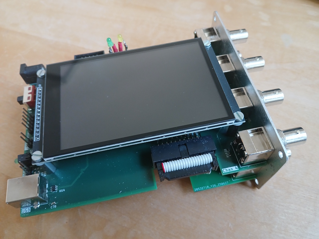
The device consists of three parts: The main PCB (130mmx100mm), the 4” TFT display which is mounted on top of it and a small 40mmx100mm PCB for two additional BNC connectors and the IDC connector. The small PCB is connected to the main PCB by a ribbon cable.
All connections are on the left and right side of the device. Two LEDs on the top of the device signal the “wait for trigger” and the “running” state to the user.
The design was meant to fit in an extruded aluminum enclosure I found on AliExpress.
Circuit design
The device is powered with 5V via a barrel jack socket. A DC-DC converter chip converts the 5V to the 3.3V supply for the MCU and the FPGA.
The MCU is a Stm32F446RE microcontroller with an attached CAT24C256 Eeprom for storing persistent data. The MCU and the FPGA, a 10M08SCE144C8G, communicate via Uart.
All outputs and inputs are buffered with 74AHCT14 Schmitt trigger chips and protected by ESD diodes. The output impedance is 50 Ohm.
The device can be remote controlled via its USB-B connector. The schematics can be found on the download page.
PCBs
The main PCB is a standard 4 layer board, the smaller satellite PCB is with two layers. I had the boards manufactured and soldered the parts myself.
Firmware
The eight channels can be configured independently. Each channel can be set as periodic and inverted. The channel modes are
Clock (always periodic) with parameters
Frequency
Duty cycle
PhasePulse with parameters
Delay
Pulse
PauseDouble Pulse with parameters
Delay
Pulse1, Pause1
Pulse2, Pause2Uart with parameters
Baud rate
String
Data Bits
Stop Bits
ParityBitstream with parameters
Bit duration
Binary StringPulse Train with parameters
List of pulse/pause timesNumber with parameters
Bit duration
Value
Bits
LSB firstPWM with parameters
Frequency
Phase0
Trigger sources:
- Auto
- Bus
- External
- External Gate
- User(GUI)
Device Limits
Max. 10000 transitions
Pulse width between 15ns and 10s
Frequencies between 1Hz and 65MHz
PLL clock variation between 120MHz and 260MHz
Remote Control Interface
The device can be remote controlled via its USB interface. To a host it is visible as a composite USB device with a USBTMC interface and a CDC (serial) interface. The language used is SCPI.
Example:
Set the clock frequency of channel 3 to 4MHz:
CHANnel3:CLOCk:FREQuency 4MHz
Read back value:
CHANnel3:CLOCk:FREQuency?
→ returns 4000000.000000
This is a list of selected commands. To get the full list use command „SYSTem:HELP:HEADers?“.
| [:SOURce]:STATe? | Set/get automatic signal generation state |
| [:SOURce]:GENerate | Compute signal |
| [:SOURce]:RUN | Start signal output |
| [:SOURce]:STOP | Stop signal output |
| [:SOURce]:PERiodic[:STATe]? | Set/get periodic state of signal |
| [:SOURce]:CLOCk:MODE? | Set/get clock mode (AUTO|DEFault|USER) |
| [:SOURce]:CLOCk? | Set/get clock frequency |
| [:SOURce]:CLOCk:ACTual? | Get actual clock frequency |
| [:SOURce]:DPRogramming[:STATe]? | Set/get direct programming state |
| [:SOURce]:DPRogramming:DATA | Set direct programming data |
| [:SOURce]:CHANnel | Set/get channel mode (OFF|CLOCk|PULSe|DPULse|UART|BITStream|PTRain|NUMBer|PWM) |
| [:SOURce]:CHANnel | Set/get channel periodic state |
| [:SOURce]:CHANnel | Set/get channel inverted state |
| [:SOURce]:CHANnel | Set/get channel clock frequency |
| [:SOURce]:CHANnel | Set/get channel clock phase |
| [:SOURce]:CHANnel | Set/get channel clock duty cycle |
| [:SOURce]:CHANnel | Set/get channel pulse delay |
| [:SOURce]:CHANnel | Set/get channel pulse pusle duration |
| [:SOURce]:CHANnel | Set/get channel pulse pause duration |
| [:SOURce]:CHANnel | Set/get channel double pulse delay |
| [:SOURce]:CHANnel | Set/get channel double pulse pulse duration |
| [:SOURce]:CHANnel | Set/get channel double pulse pause duration |
| [:SOURce]:CHANnel | Set/get channel Uart number of bits (DBIT7|DBIT8) |
| [:SOURce]:CHANnel | Set/get channel Uart numer of stop bits (SBIT1|SBIT2) |
| [:SOURce]:CHANnel | Set/get channel Uart baud rate (BR50|BR110|BR150|BR300|BR1K2|BR2K4|BR4K8|BR9K6|BR19K2|BR38k4|BR58K6|BR115K2|BR230K4|BR460K8|BR921K6|BR2M|BR3M) |
| [:SOURce]:CHANnel | Set/get channel Uart parity (NONE|EVEN|ODD) |
| [:SOURce]:CHANnel | Set/get channel Uart string |
| [:SOURce]:CHANnel | Set/get channel bitstream bit duration |
| [:SOURce]:CHANnel | Set/get channel bitstream string |
| [:SOURce]:CHANnel | Set/get channel pulse train list of durations |
| [:SOURce]:CHANnel | Set/get channel number value |
| [:SOURce]:CHANnel | Set/get channel number bits |
| [:SOURce]:CHANnel | Set/get channel number LSB first state |
| [:SOURce]:CHANnel | Set/get channel number bit duration |
| [:SOURce]:CHANnel | Set/get channel pwm frequency |
| [:SOURce]:CHANnel | Set/get channel pwm phase |
| TRIGger:SOURce? | Set/get trigger source (AUTO|BUS|EXTernal|GATE|USER) |
| TRIGger:EDGE? | Set/get trigger edge (RISing|FALLing) |
| TRIGger:ARM | Set trigger armed state |