The Controller Board is the brains of the box. We are going to take a look at it now.
The Controller Board
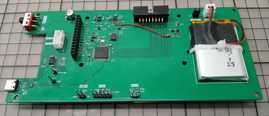
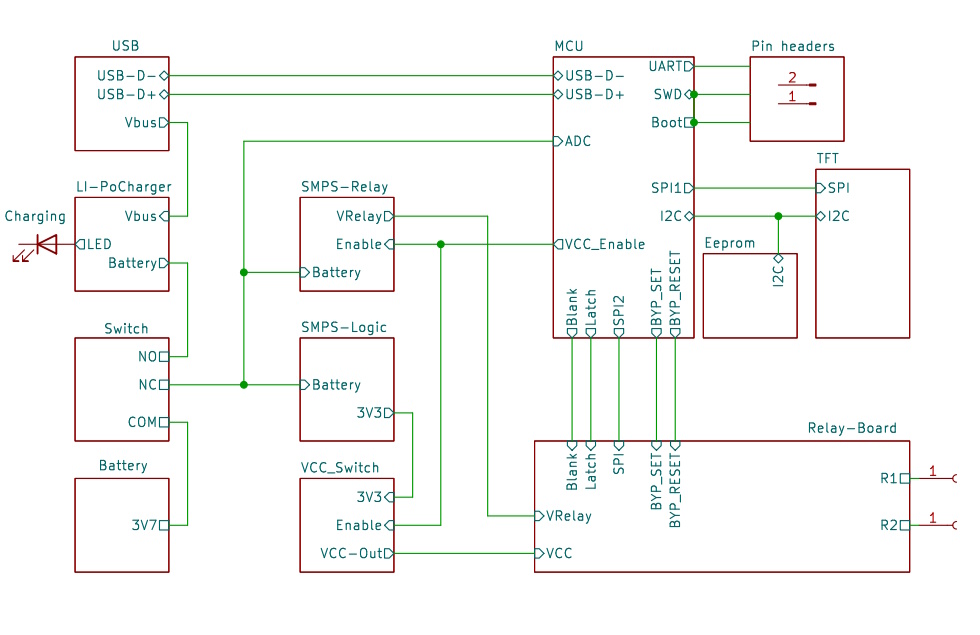
The controller board is a double-layered PCB with assembly from one side. The microcontroller, a 64 pin STM32F446RE runs at the moderate clock speed of 72 MHz to keep its power consumption low. The system uses around 100mA in normal operation and around 13mA in sleep mode.
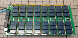
With the 1100mAh Li-Po battery this guarantees several hours of operation even if sleep mode is not enabled. As the relays keep their states even without power, the device may be switched off if not in use and the set resistance will still be still retained.
With the sliding switch on the controller board the device can be put in the On state or in the Charging state. It is not possible to charge the battery while the device is running. An LED on the front panel lights up while the battery is being charged.
To save on battery power the supply voltages for the relay board can be disconnected under firmware control.
The user interacts with the device using the 2.8“, 320×240 pixel TFT capacitive touch display which uses a ILI9341 chip for the display and an FT6336 for the touch functions.
User settings and calibration data are stored in an Eeprom. Remote control is possible via the USB-C connection which also provides the power to charge the battery.
A SWD debug connector allows debugging with a ST-Link interface. Debugging messages can be output via a UART pin. The device can be put into Boot Mode with a jumper across the two boot pins. This way the firmware can be updated without an IDE by using ST’s STM32CubeProgrammer software and USB.