Working on a project for an LCR meter (I may write about this in a future post) I realized that if calibration could be automated it would be much faster and also less error prone. So I put the LCR meter on the back burner and set out to build a programmable decade resistor first.
Overview
Browsing the Internet I came across Sebastian Harnisch’s project on https://sebastianharnisch.de/progammable-resistance-decade from which I took many ideas. A great shout-out to Sebastian for his detailed explanation of his project.
What I had in mind, however, was a more compact device which would use less space on the work bench and would operate on a battery instead off the mains power supply.
These are the features of the box I wanted to build:
-
Resistance range up to 10 MOhm with a resolution of 0.1 Ohm.
-
250mW Resistors, 0.1%
-
Using latching relays, which will keep their settings without being powered
-
Rechargeable, single cell Li-Po battery
-
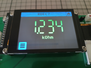
2.8“ capacitive touch display (no buttons or rotary encoder)
-
Remote control via USB
- Budget-friendly building costs
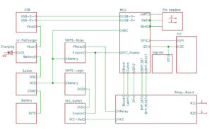
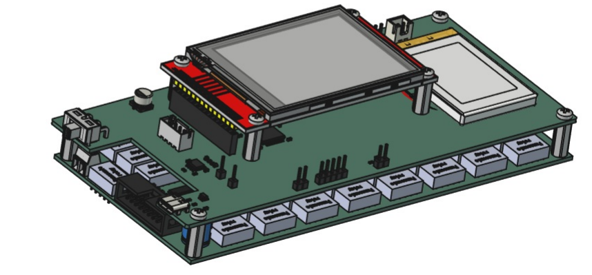
The above picture shows a FreeCad design of the assembly I came up with. The system consists of two PCB modules, stacked on top of each other and the TFT display piggybacked on top. Controller board and relay board are connected with a ribbon cable.
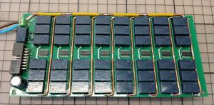
The board at the bottom is the relay board with 8×6 latching relays for the 8 decades and a bypass relay for resistances below 1 Ohm. The driver chips for the relays are 16-channel LED drivers TLC59284 from Texas Instruments. The serial interfaces of these chips are daisy-chained.
The MCU on the controller board is an STM32F446. It controls the decade relays using one of its SPI interfaces and the TFT display with the other.
The battery feeds two buck-boost converter chips, one for the 3.3V-logic supply and one for the 5V supply of the relays. The supply voltages for the relay board can be switched off to save power. The battery can be charged from the voltage on the USB-C port using a LI-Po battery charger chip.
A sliding switch puts the device into either the On state or the Charging state.
The TFT display is a 2.8“ 320×240 LCD display with capacitive touch function.
The device can be remote controlled via its USB-C connector.
Topology
As can be seen in the diagram below the total resistance at the terminals of the box is the sum of the resistances of its 8 decades (including the contact resistances of the relays in each decade) and the contribution of the parasitic resistance of the connecting tracks.
For small resistance values the track resistances in the „long loop“ become dominant. A bypass relay shorts decades 2-8 reducing the effect of these parasitics.
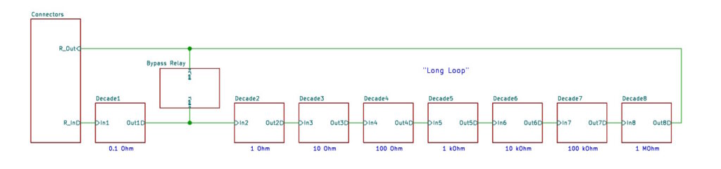
The topology is identical for all decades and follows Topology B as described in Sebastian Harnisch’s post https://sebastianharnisch.de/programmable-decade-resistor-topology.To keep the BOM concise all resistors in a decade have identical values 2R = 0.2Ohm, 2Ohm … 2MOhm.
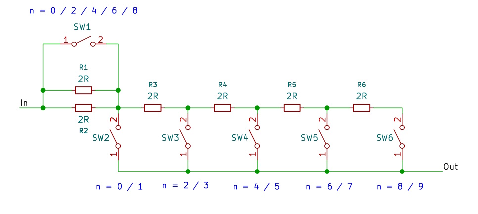
From the diagram it can be seen that the resistance of a decade is determined by the leftmost closed vertical switch and the state of SW1 which is open for odd values of n. For a set value of n=0 two relay contacts are in the loop which has to be taken into account when setting small resistance values.
Parasitic Resistances
The parasitic resistance of a trace connecting two decades in our layout is on the order of 80 mOhm. (track width = 1mm, standard copper thickness 1oz/ft2, length = 160mm). With a thick copper wire added to one part of the track length this value comes down to ~40 mOhm.
The total for all 8 decades is therefore 320 mOhm.
According to the data sheet the contact resistance of a relay is 50 mOhm. As we connect both switches of a relay in parallel this value reduces to 25 mOhm.
Adding it all together the combined resistances of the 8 connecting tracks and 16 relays gives us a value of 720 mOhm for the resistance of the „long loop“ Rll. The exact value can be measured from the outside if all decades are set to a value of zero.
Without additional measures this would be the minimum resistance which can be set on the device. Using the bypass relay Rsl, the resistance of the „short loop“ is the trace resistance of one decade + 3 x relay resistance = 40 mOhm + 75mOhm = 115 mOhm.
Switching Strategy
As a first switching strategy we can do the following:
-
For set values Rs smaller than 1Ohm + Rsl: Turn on the bypass relay and use decade 1 to set the desired value. Take Rsl the parasitics of the „short loop“ into account.
-
For values greater than that: Turn the bypass relay off. Compute the expected total resistance taking the parasitics into account. Subtract the value of the parasitics and set the relays according to this new value.
For this to work Rll must be smaller than Rsl + 1 Ohm. Otherwise decade 1 will not be able to compensate for Rll. Additional copper wires on parts of the tracks help to meet this requirement.
What happens, if Rll does not fulfil this requirement? As an extreme example let’s assume Rll = 10 Ohm, Rsl = 0.1 Ohm and the set value Rs is 1.3 Ohm.
As Rs > 1+ Rsl the bypass relay is open and the Rrel = Rs – Rll = 1.3 Ohm – 10 Ohm = -8.7 Ohm which clearly is impossible to set.